NavIC space segment · timing
Indigenous RAFS
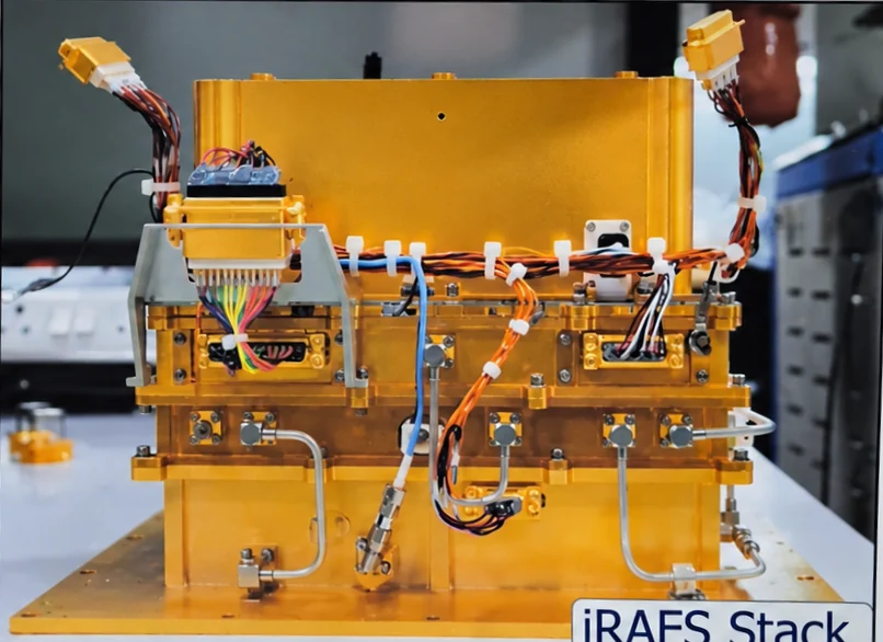
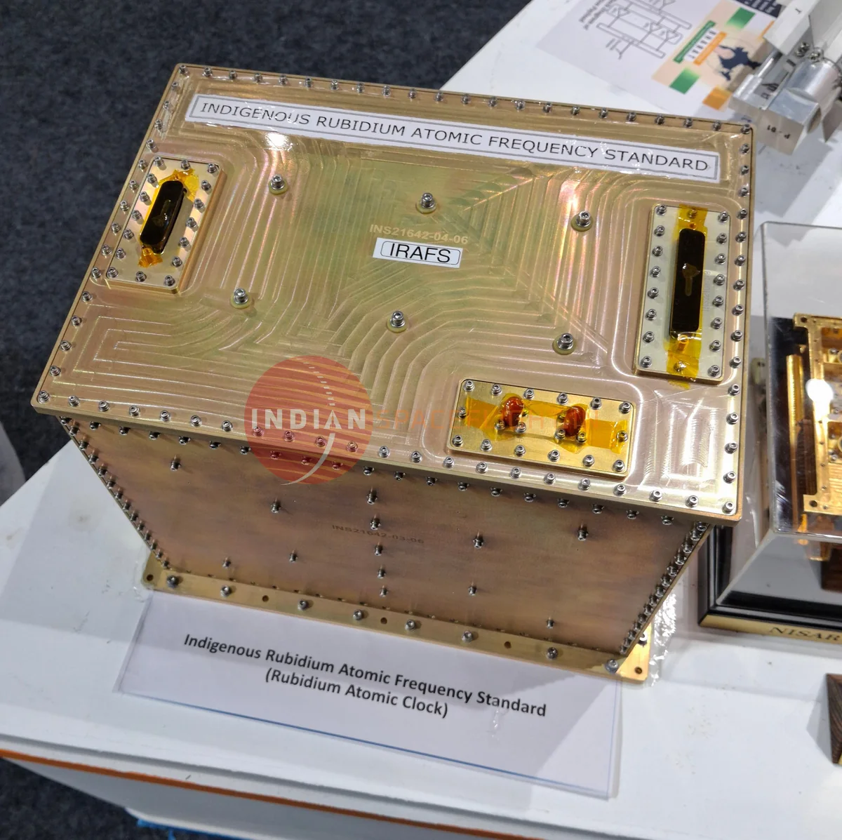
The iRAFS is the atomic clock SAC‑ISRO built so NavIC no longer depends on imported clocks. It locks a quartz oscillator to a hyperfine transition of rubidium‑87 and hands the navigation payload a 10 MHz signal that stays stable to a few parts in 10¹⁴ over hours.
- Built by
- Atomic Clock Development Division, Space Applications Centre (SAC‑ISRO), Ahmedabad[1]
- First flight
- NVS‑01 on GSLV‑F12, 29 May 2023[1]
- In service
- Drives NVS‑01’s navigation signals; NavIC service since 4 July 2023[2]
- Reference atom
- Rubidium‑87, ground‑state hyperfine line at 6 834 682 611 Hz
- Ground stability
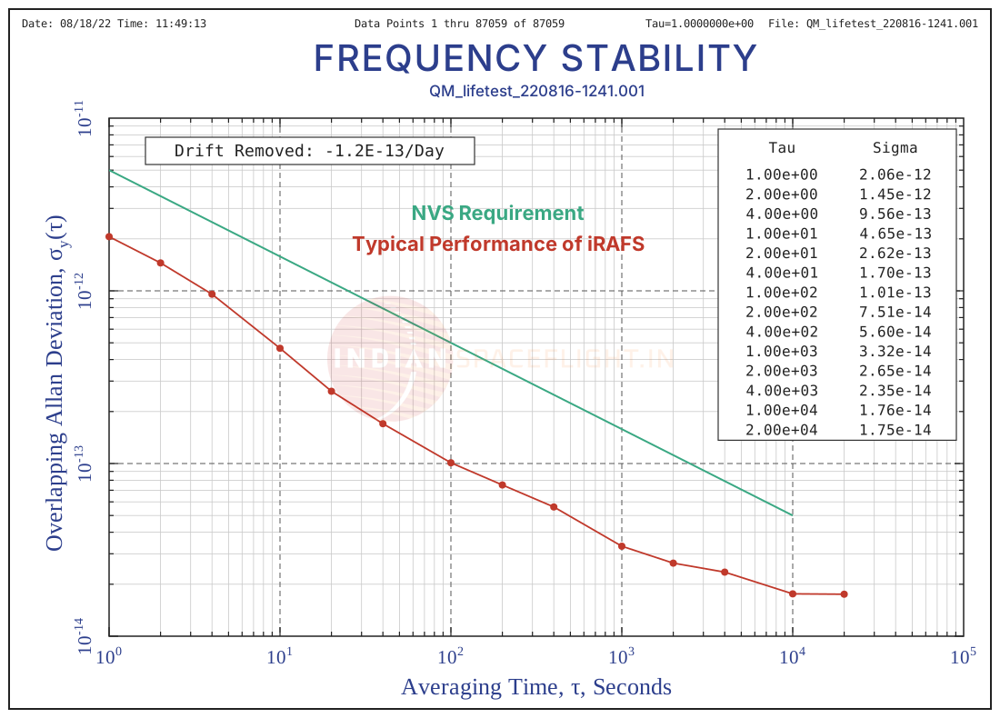
- Below 5 × 10⁻¹⁴ at 10 000 s (qualification model)[1]
Why India built its own clock
A navigation satellite is a clock that broadcasts its time. A receiver turns the signal’s travel time into distance, so every nanosecond of clock error is about 30 cm of range error. Between ground updates the onboard clock has to keep time by itself, and that is the job of the rubidium atomic frequency standard (RAFS).
Every first‑generation IRNSS satellite carried three imported RAFS made by SpectraTime of Switzerland, now part of Safran. All three on IRNSS‑1A had failed by early 2017. Europe’s Galileo, which also used SpectraTime clocks, reported 9 of its 72 orbiting clocks failed in the same period, and ESA linked the rubidium failures to probable short circuits.[7][8][9]
Failures kept thinning the constellation. On 2 Jul 2025, an RTI response summarized on X by indianspaceflight.in founder solidbosters2 counted four birds toward PNT, including IRNSS‑1F with one clock left, with zero margin if another clock stopped. IRNSS‑1F’s last rubidium clock failed in March 2026, so only IRNSS‑1B, IRNSS‑1I, and NVS‑01 remain for navigation today. Six Gen‑1 spacecraft, 1A, 1C, 1D, 1E, 1F, and 1G, eventually lost all three imported clocks. Parliamentary answers and press reports described the same pattern.[28][5]
SAC’s answer is the indigenous RAFS. Its first flight model went up on NVS‑01 in May 2023 and has driven that satellite’s navigation signals since July 2023. Each Gen‑2 (NVS) satellite carries four RAFS: one iRAFS built by SAC‑ISRO and three imported SpectraTime/Orolia units (Safran). SAC’s ICG‑17 slides show NVS‑01 flying a redundant Safran RAFS alongside its iRAFS; ISRO mission material describes the same four‑clock layout on NVS‑02 and NVS‑03.[1][2][3][4]
Programme history, the Jul 2025 RTI clock disclosure, and every launch are on the NavIC overview.
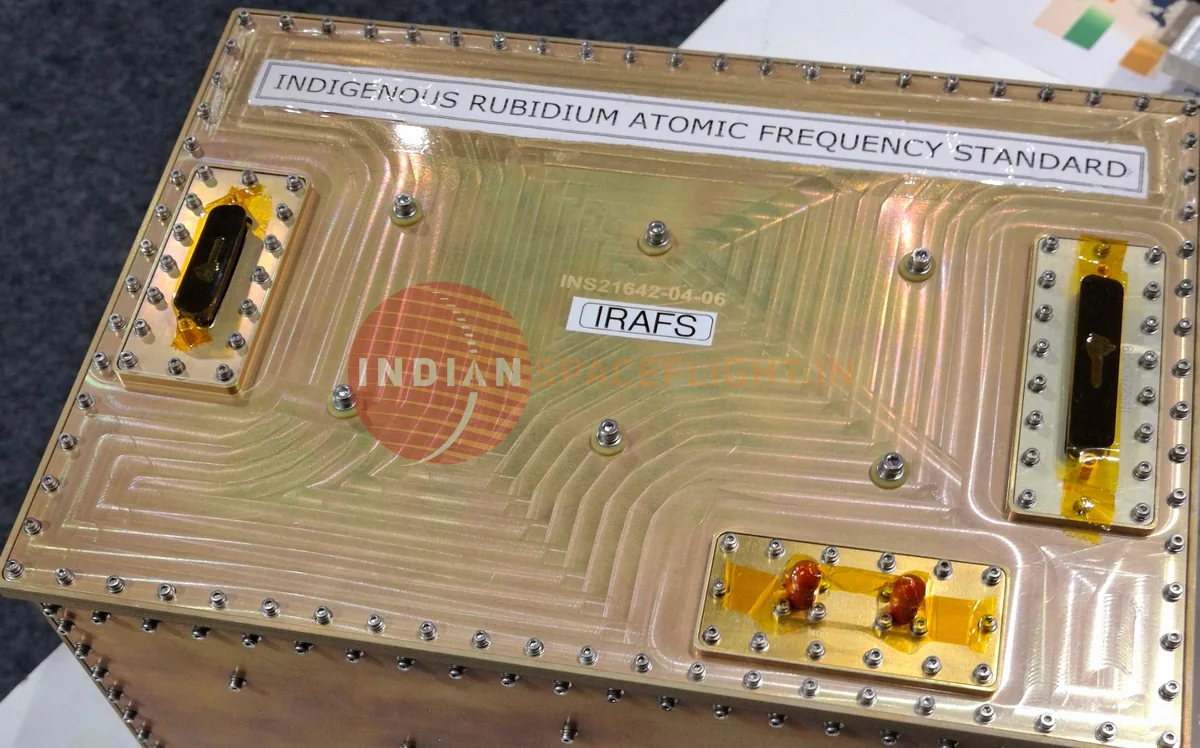
Inside iRAFS
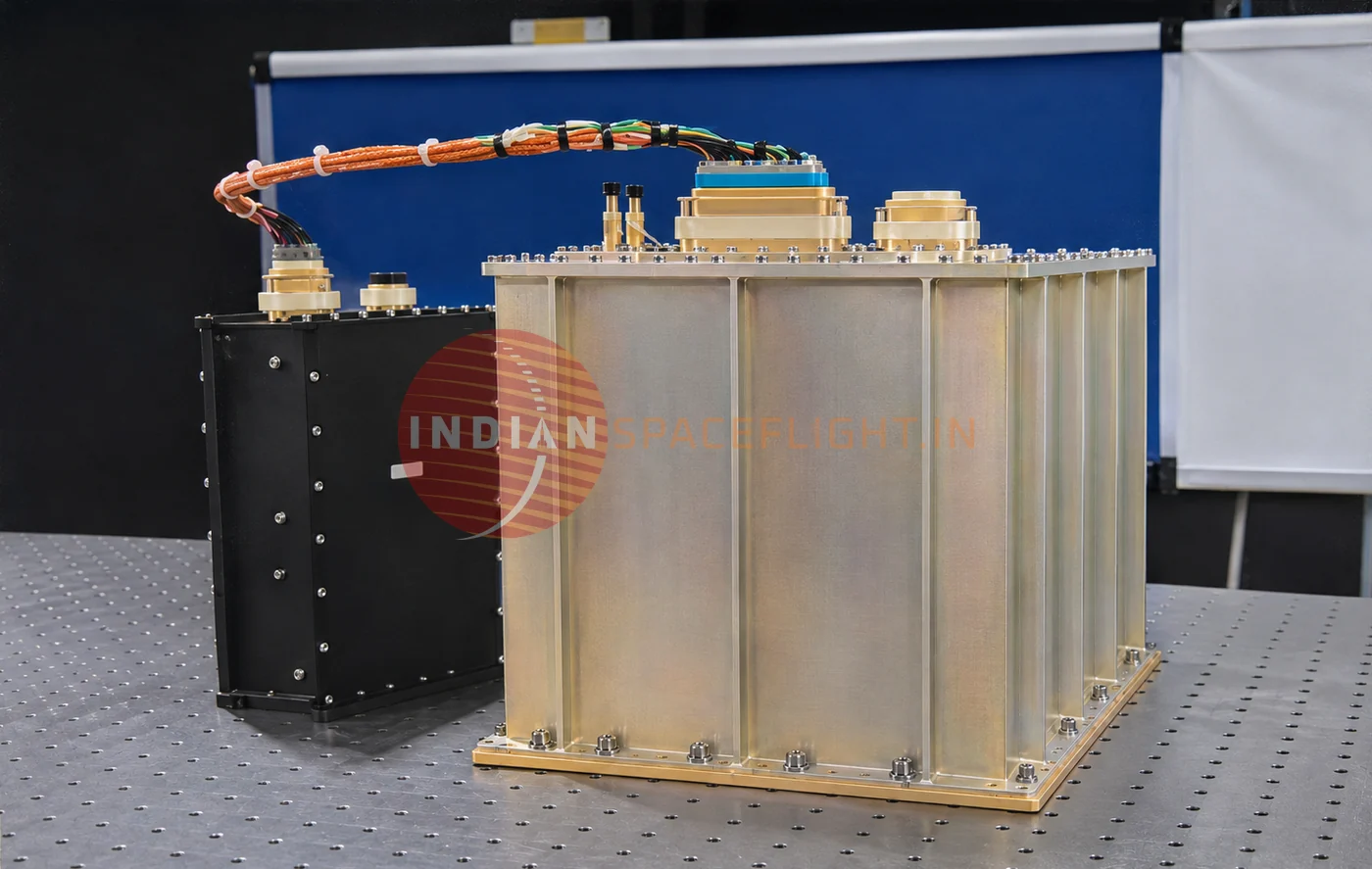
Hardware from SAC’s exhibit poster, and the block diagram that ties it together.
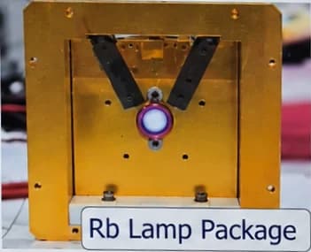
Rb lamp package
Holds the rubidium discharge lamp. An RF circuit keeps the Rb‑87 vapour glowing (the violet spot), giving the 780 and 795 nm light that pumps the atoms.
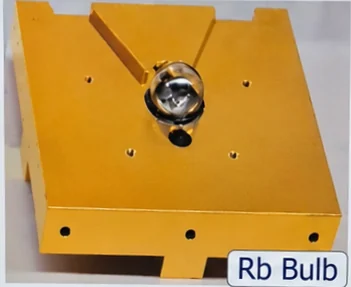
Rb bulb
The lamp bulb itself: a small glass sphere with rubidium inside, seated in its temperature‑controlled mount.
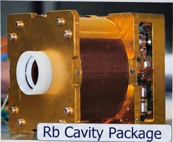
Rb cavity package
A microwave resonator near 6.835 GHz (TE₀₁₁ mode) wrapped in the copper C‑field winding. The resonance cell sits inside, facing the lamp.
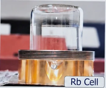
Rb cell
The glass resonance cell. SAC describes the physics package as lamp‑pumped with an integrated filter cell, so filtering the light and probing the atoms happen in one cell.
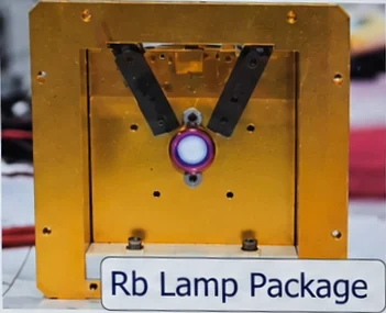
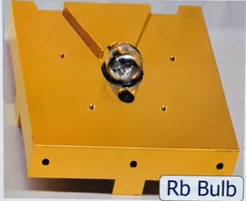
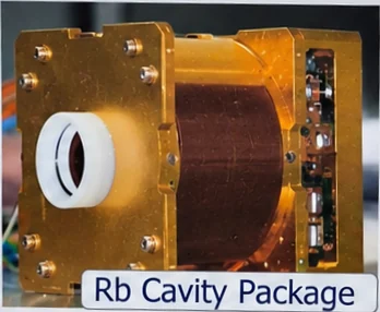
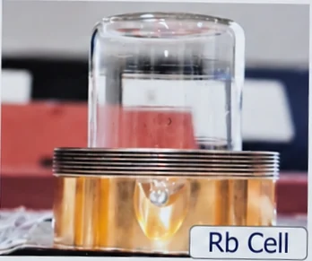
Photos: SAC‑ISRO exhibit poster, photographed by indianspaceflight.in.
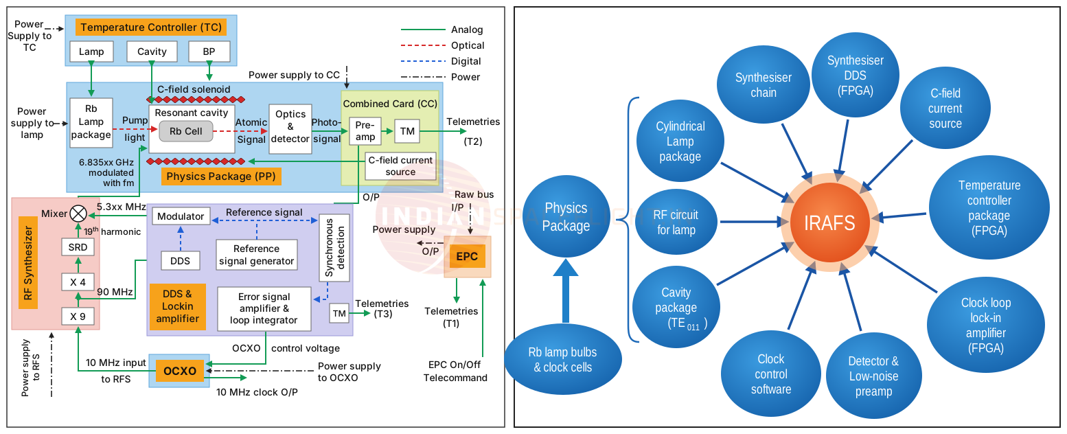
Physics package
- Rb lamp bulbs and clock cells
- Glass parts filled with rubidium: the lamp bulb that makes the pump light and the cell that holds the atoms.
- Cylindrical lamp package
- Lamp housing, held at its own set temperature.
- RF circuit for lamp
- Drives the discharge that makes the lamp glow.
- Cavity package (TE₀₁₁)
- Microwave cavity, cell and C‑field winding inside magnetic shields.
- Detector and low‑noise preamp
- Turns the light leaving the cell into a clean electrical signal.
Electronics
- Synthesiser chain
- Multiplies the OCXO’s 10 MHz up to 6 840 MHz.
- Synthesiser DDS (FPGA)
- Digitally tunable offset of about 5.3 MHz that lands the probe on the atomic line and adds the modulation.
- C‑field current source
- Sets the weak magnetic field that isolates the clock transition and trims its frequency.
- Temperature controller (FPGA)
- Holds the lamp, the cavity and a third zone (BP on SAC’s diagram) at set temperatures.
- Clock‑loop lock‑in amplifier (FPGA)
- Demodulates the detector signal into the error that steers the OCXO.
- Clock control software
- Sequences the clock and manages the loop; SAC lists it as a subsystem of its own.
How it keeps time
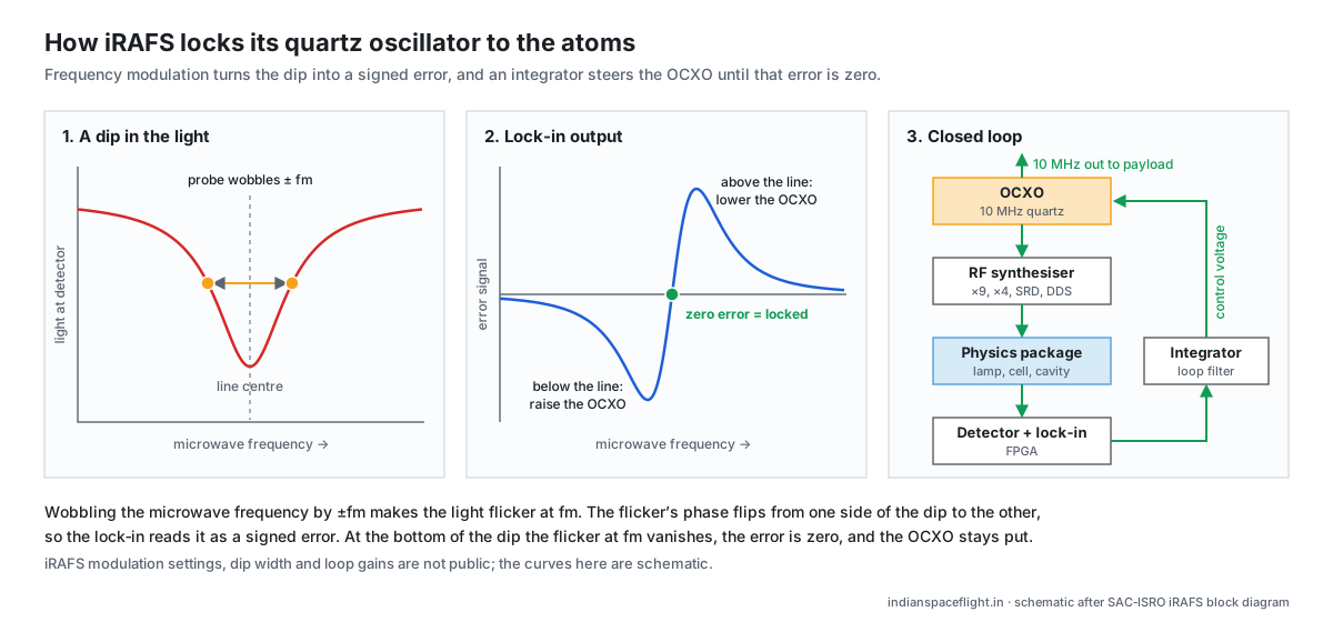
Atoms set the frequency, quartz delivers it. The loop below runs continuously on board.
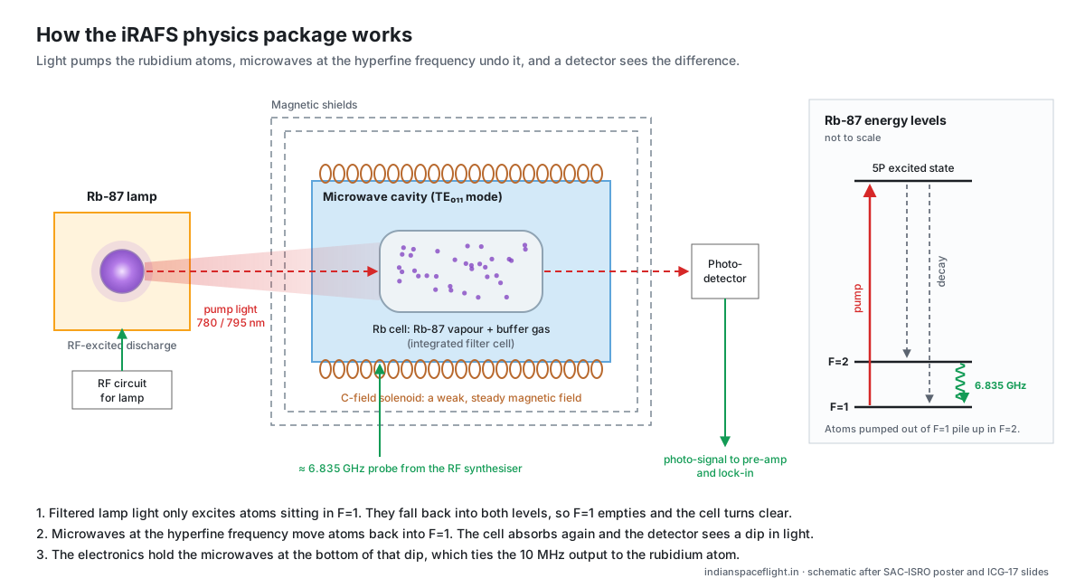
- 1
Quartz makes 10 MHz
An oven‑controlled crystal oscillator (OCXO) is the clock’s flywheel: very clean over seconds, but it drifts over hours.
- 2
Multiply by 9, then by 4
10 MHz becomes 90 MHz, which also clocks the DDS, and then 360 MHz.
- 3
Step‑recovery diode comb
The SRD turns 360 MHz into a comb of harmonics. The 19th sits at 6 840 MHz.
- 4
Mix down to the line
Subtracting about 5.3 MHz from the DDS lands the probe at 6 834.68 MHz, the rubidium line. The DDS also wobbles it at the modulation frequency fm.
- 5
Ask the atoms
The probe drives the cavity. When it sits on the line, the cell absorbs more lamp light and the detector current dips.
- 6
Correct the quartz
The lock‑in reads which side of the dip the probe is on. The loop integrator turns that into the OCXO control voltage, so the 10 MHz output inherits the atoms’ long‑term stability.
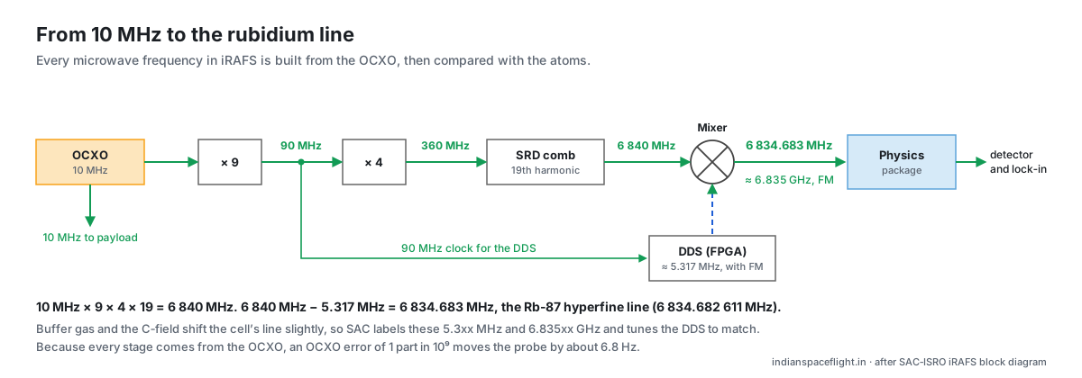
Try it: detune the quartz
Every stage is built from the OCXO, so its error scales all the way up. Move the slider, then close the loop and watch the atoms pull it back.
OCXO
10 MHz
+60.0 mHz
× 9
90 MHz
+540.0 mHz
× 4
360 MHz
+2.16 Hz
SRD 19th harmonic
6840 MHz
+41.0 Hz
Probe (− DDS ≈ 5.317 MHz)
6834.682611 MHz
+41.0 Hz
Probe offset from the Rb‑87 line: +41.0 Hz
Probe is above the line. The lock‑in reads a positive error and the integrator lowers the OCXO control voltage.
How stable is it
Allan deviation of the iRAFS qualification model on the ground, against the NVS requirement and published figures for other systems’ clocks. Tap a point for its value.
Loading stability chart…
In orbit, DLR and Septentrio measured NVS‑01’s clock against a hydrogen maser in Japan: beyond 20 s it matches these ground tests and does better at longer times, and it beats every first‑generation IRNSS clock at every averaging time.[6] SAC’s own on‑board comparison against the redundant Safran RAFS showed a relative drift of 2.4 × 10⁻¹³ per day.[1] Open SAC’s plot (redrawn)
How it compares with other countries’ clocks
Every system mixes clock types for redundancy. Figures come from different methods, so read them as a class, not a ranking.
| Clock type | Physics | Stability class | Flown on | Trade‑off |
|---|---|---|---|---|
| Rubidium (RAFS) | Rb‑87 hyperfine line, 6.835 GHz, probed in a vapour cell | Best flight units reach about 2 × 10⁻¹⁴ at 10⁴ s | NavIC (both generations), GPS, Galileo, BeiDou‑3, GLONASS‑K, QZSS | Small and light (Galileo’s RAFS is 3.4 kg). The frequency ages by around 10⁻¹³ per day, which the ground segment keeps modelling.[13][12][11][16] |
| Passive hydrogen maser | Hydrogen hyperfine line, 1.420 GHz, in a storage bulb | Below 1 × 10⁻¹⁴ beyond 10⁴ s | Galileo (two per satellite), BeiDou‑3; in test for GLONASS‑K2 | Far less drift than rubidium, but Galileo’s maser is about 18 kg and 26 litres.[12][10][16][22] |
| Cesium beam | Cs‑133 hyperfine line, 9.193 GHz, in an atomic beam | GLONASS‑M specified 1 × 10⁻¹³; the latest units reach 2.4 × 10⁻¹⁴ per day | GLONASS‑M (three per satellite), GLONASS‑K, GPS Block IIF (one of three clocks) | Very low drift, but heavier, and the beam tube’s caesium supply limits its life.[22][23][19] |
| Quartz OCXO | Mechanical resonance of a crystal held in an oven | Excellent from fractions of a second to seconds; drifts over hours | Inside every atomic clock as its flywheel, and in every GNSS receiver | This is why receivers solve their own clock error as a fourth unknown and need four satellites. |
| System | Clocks per satellite | Maker | Published stability | Track record |
|---|---|---|---|---|
| NavIC Gen‑2 (NVS)India | 4 × RAFS (1 × iRAFS + 3 × imported SpectraTime/Orolia) | SAC‑ISRO (iRAFS); SpectraTime/Orolia, Safran (imported RAFS) | Ground QM below 5 × 10⁻¹⁴ at 10⁴ s. In orbit, DLR found NVS‑01’s clock matches its ground tests beyond 20 s and beats every Gen‑1 clock. | iRAFS has driven NVS‑01’s signals since July 2023.[1][6][3] |
| NavIC Gen‑1 (IRNSS‑1)India | 3 × RAFS | SpectraTime (Switzerland, now Safran) | Rubidium class. In orbit, DLR measured them less stable than NVS‑01’s iRAFS at every averaging time. | Failures across the fleet: IRNSS‑1A lost all three by 2017, IRNSS‑1F its last in March 2026.[6][7][5] |
| GalileoEuropean Union | 2 × RAFS + 2 × passive hydrogen maser | SpectraTime / Safran (RAFS, maser physics), Leonardo (maser) | RAFS specified at 5 × 10⁻¹²/√τ, drifting under 10⁻¹³ per day in orbit. Maser below 10⁻¹⁴ beyond 10⁴ s. | By January 2017, 9 of 72 clocks had failed (3 RAFS, 6 masers). No satellite was lost, because each carries four.[10][11][12][9][13] |
| BeiDou‑3China | Rubidium and passive hydrogen maser | Chinese‑built | MEO clocks 4.0 × 10⁻¹⁴ at 1 000 s. Masers reach around 10⁻¹⁵ over a day; rubidium drifts around 10⁻¹³ per day. | Moved to domestic clocks for BeiDou‑3. ESA said in 2017 that China had used the same SpectraTime clocks as Galileo.[14][15][16][8] |
| GPSUnited States | Block IIF: 2 Rb + 1 Cs; GPS III: 3 enhanced Rb | US industry (Excelitas rubidium on GPS III) | GPS IIF rubidium around 1 × 10⁻¹⁴; GPS III rubidium reached about 10⁻¹⁵ in the lab. | A GPS IIF cesium clock failed about a month after it was switched on.[18][20][19][21] |
| GLONASSRussia | GLONASS‑M: 3 × Cs; GLONASS‑K: Cs and Rb; maser in test for K2 | Russian‑built | GLONASS‑M daily stability improved from 1 × 10⁻¹³ to 2.4 × 10⁻¹⁴. GLONASS‑K rubidium: 4 × 10⁻¹⁴ per day. | The only major GNSS built mainly around cesium.[22][23] |
| QZSSJapan | Rubidium; QZS‑1 flew two (one spare) | Same rubidium type as GPS Block IIF | In orbit: 6.6 × 10⁻¹⁴ at 1 000 s, 5.4 × 10⁻¹⁴ at 10⁴ s. | A hydrogen maser was dropped in 2006. QZS‑1’s second clock became unstable in 2012 and it switched to the spare.[24][25][26] |
In orbit, from NASA CDDIS data
What the broadcast messages say about each NavIC clock today, and how NavIC compares with other GNSS in the same daily files.
Loading broadcast clock data…
What the broadcast data can and cannot tell

In the files
- The clock rate (af1) ISRO uploads for each satellite, every update, every day.
- How well one update predicts the next one two hours later: our 2‑hour prediction error.
- Frequency steps, health flags and days a satellite goes silent.
Not in the files
- Which RAFS on an NVS satellite is active at any moment.
- The clock’s true Allan deviation. That needs carrier‑phase data against a hydrogen maser, as DLR did for NVS‑01.
- Clock telemetry such as lamp voltage or OCXO control voltage.
- Keep clock labels honest
Set navic_satellites.clock_type to “3 × SpectraTime RAFS” for Gen‑1 and “4 × RAFS (1 × iRAFS + 3 × imported)” for NVS, and change it when ISRO announces a clock switch.
- Log frequency steps
A jump in the daily clock rate usually means a clock switch or an adjustment. Recording it as an event would flag it on the status page.
- Look for precise clock products
If an IGS MGEX analysis centre publishes NavIC precise clocks, they would give a real Allan deviation from a few minutes upward instead of a broadcast proxy.
Terms on this page
- Allan deviation σ(τ)
- How much the clock’s average frequency wanders between neighbouring windows of length τ. Smaller is more stable. σ × τ gives a rough idea of the time error built up over τ.
- Fractional frequency
- Frequency error divided by the nominal frequency. 1 × 10⁻¹³ means a clock gains or loses about 8.6 ns per day.
- Aging (drift)
- Slow, steady change of a clock’s frequency over days. Rubidium clocks age by around 10⁻¹³ per day; the ground segment models it in the broadcast af1 and af2.
- C‑field
- A weak, steady magnetic field across the cell. It separates the magnetic sub‑levels so only the field‑insensitive clock transition is probed, and lets engineers trim the frequency.
- OCXO
- Oven‑controlled crystal oscillator. The quartz flywheel that the atoms correct.
- Lock‑in amplifier
- Picks out a small signal at a known modulation frequency, with its phase. In iRAFS it runs in an FPGA.
Sources
Numbers on this page link here. Corrections are welcome on the forum.
- SAC‑ISRO, Performance of IRAFS on‑board NVS‑01 NavIC satellite (ICG‑17, Oct 2023)
- ISRO, NVS‑01 performance: L1 signal, data and indigenous atomic clock (ICG‑17, Oct 2023)
- ISRO, GSLV‑F15 / NVS‑02 mission brochure (Jan 2025)
- PTI via The Week, GSLV places NVS‑03 in its designated orbit (31 Oct 2026)
- ThePrint, NavIC setback after IRNSS‑1F’s last clock stopped (Mar 2026)
- Steigenberger, Sleewaegen and Montenbruck (DLR, Septentrio), New NavIC clock outperforms previous generation, GPS World (Sep 2023)
- GalileoGNSS, Time is everything with GNSS (2017): IRNSS‑1A lost all three RAFS
- Space.com, Ten atomic clocks have failed on Galileo satellites (Jan 2017)
- Inside GNSS, ESA puts brave face on Galileo clock failures (Jan 2017)
- TUM, redshift test with Galileo clocks: two rubidium and two maser clocks per satellite
- INRIM, GIOVE‑A and GIOVE‑B in‑orbit RAFS and PHM results
- SPIE 10567 paper citing Galileo RAFS and PHM size and stability
- GPS World (Oct 2021), Orolia clocks for Galileo second generation
- Lv et al., Characteristics of BeiDou‑3 experimental satellite clocks (Remote Sensing, 2018)
- Geng et al., Analysis of BDS‑3 onboard clocks from GFZ products (Remote Sensing, 2022)
- Wuhan University, Frequency performance of BeiDou‑3 satellite atomic clocks
- BDS‑3 rubidium and hydrogen clocks from inter‑satellite links (Springer, 2023)
- Inside GNSS, GPS III: three enhanced rubidium clocks per satellite
- Inside GNSS, GAO on the GPS IIF cesium clock failure
- GPS World, GPS IIF and GPS III rubidium stability
- Airforce Technology, Excelitas rubidium clocks for GPS III SV1
- ISS‑Reshetnev, GLONASS‑M clocks and GLONASS‑K2 maser plans (ICG‑12, 2017)
- GPS World, Directions 2017: new GLONASS capabilities for users
- Xie et al., Characteristics and performance of QZSS onboard clocks (Sensors, 2019)
- JAXA, Michibiki (QZS‑1) rubidium clock status
- Wikipedia, Quasi‑Zenith Satellite System
- SAC iRAFS qualification‑model life test, 16–18 Aug 2022 (plot redrawn by indianspaceflight.in)
- indianspaceflight.in (solidbosters2), NavIC atomic clock RTI summary on X (2 Jul 2025); later parliamentary reporting